Sunday, December 30, 2012

Ch 7: The Fuselage Exterior - NACA Scoop

Now that the sides and bottom are glassed and assembled it's time to shape and glass the exterior.  At the completion of Ch 7, I'll have a rigid fuselage, or a least most of one, that I can actually sit in and make airplane noises.  It starts with building the NACA scoop.

The Scoop on the NACA Scoop
The NACA Scoop is on the bottom of the fuselage and its job is to pull in air during flight to cool the engine.  There are many archive emails on the Cozy Builders Forum discussing the plans NACA scoop and ways to ensure it works well.  You'll also find many opinions about the plans updraft cooling (air coming up from the bottom) vs down draft cooling (air coming down from the top) and everything surrounding it.  My research indicates that the plans updraft cooling works just fine provided the scoop is built correctly and you make sure your engine baffling has a good seal to direct all the available cooling air across the cylinders and out the the cowling.

A review of the Cozy archives and a couple of Central State Association newsletters (July '90 & Apr '11, reveals a few key items to keep in mind when building the scoop.  Also be sure to download the Cooling Forum Slides from Oshkosh 07 for some good info on cooling.  Key points I noted are...
  1. The entry point (throat) of the scoop ramp should not be a point...it should be approximately 1" or so wide for our Cozy. 
  2. The throat should provide a smooth entry with no discernible joggle or dip...a joggle will create air flow separation and disrupt the smooth flow into the scoop. When you're done contouring the scoop, use a straight edge and rock it over the throat entrance. If you hear the ruler click against the fuselage rather than smoothly rock back and forth, then there is a step or joggle that needs to be eliminated. 
  3. The intersection of the scoop wall and the bottom of the fuselage should be a sharp 90 degree angle. 
  4. The intersection of the scoop wall and the bottom of the scoop should be a large rounded radius. I've seen comments that the corner radius should be approx. 1/2 the height of the scoop wall at any given point.
  5. The slope for the ramp of a NACA scoop should be 5-11 degrees with optimal being 7 degrees. The Cozy scoop starts out more shallow and then curves to a steep angle (~10 degrees) between the landing gear bulkheads and the firewall as the scoop gets wider. There's really not much you can do here to change it because there is not much room between the scoop and the landing gear.
  6. The aspect ratio of the scoop along its path should be between 3 and 5. That is, the width should be 3-5 times the height. As the scoop runs back through the LG bulkheads and to the exit (into the cowl), the Cozy scoop has a ratio of around 4.8.  If you wanted, you could make it better later by extending the opening to the cowling a little below the scoop.
Building the NACA Scoop
The scoop is actually formed by building up foam around where the scoop will be.  The building starts by cutting out the template.  After I cut it out, I modified it slightly to allow for an approx. 1" throat as mentioned in #1 above.  I simply widened the tip to 1 1/8" and redrew straight lines down to where the curve starts.  You can see in the pic where the original template lines are vs the slightly widened version.

Front part of NACA Template with extra width
Close up showing 1 1/8" wide throat vs plans point

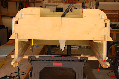
Now the template is fitted to the fuselage center-line and cutouts in the LG bulkheads.  In my case, I had to trim a bit of the firewall and aft LG bulkhead width to match the template.  The FAQs say this is likely the case and most people trim the bulkheads.  Also, based on the FAQs, I extended the foam about 7.5", up to the edge of the landing brake, to ensure the foam made it up far enough to sand straight and level back to the bulkheads.

Scoop foam cured and ready for sanding
Then, foam is cut to match the template and micro'd in place.  (TIP) I did not use the urethane foam called for in the plans.  I asked the forum about experiences with this foam and I got many folks who told me they wouldn't use it again because its too brittle.  Several of them had to fix delaminations in this area and they haven't finished the plane yet.  I decided to use 4.5 lb Last-a-foam.  It's heavier, but it sands easily and isn't nearly as brittle as the urethane.  I'll probably use this in place of all urethane foam from here out.


Back and forth, back and forth, etc., etc....

Once the foam is cured, the sanding can begin.  I built a straight 4ft sanding tool with 36" of 80 grit belt sandpaper glued in the center on the bottom.  If I did it again I would have used 40 or 60 grit to go a little faster.  It didn't take too long but you do need patience so you don't get in hurry and screw it up.  The goal is a nice flat surface the extends from just behind the landing brake to the fwd bulkhead.  A little while sanding back and forth and the scoop was level.


The NACA Scoop formed and ready for glassing.  Note this pic was taken after the shaping of the bottom corners...that's coming up.
NACA Scoop Glassed


Onward, cab

Sunday, October 7, 2012

Ch 6: Installing the Bottom

Better to be lucky than good
This post has a happy ending but it almost didn't.  The time had come to install the bottom.  All was ready and the prep went well.  I planned my work and worked my plan.  First I applied a thin layer of resin to the mating areas, then I buttered up all the mating areas on the fuselage, then to install the bottom.

With my father-in-law helping, we gently lowered the bottom onto the fuselage inserting the front first, then the back, carefully aligning with my marks to assure me everything is lined up correctly.  We then started applying some weight on top to put pressure on all the mating joints.  First we added a tool box down the center, a case of water bottles, various storage bins filled with garage accessories, even kitty litter containers I use to soak up oil spills, anything with some weight to it.  Everything was going great but as I turned to get some additional weight...CRASH!  I turned to find my fuselage hanging half off the sawhorses with items I used to add weight littered all over the floor...Oh the horror!

After a second or two of disbelief, we jumped into action establishing some new hard points to support the fuselage.  I knew I didn't have much working time left on my resin and I certainly didn't want to scrape all this off and start over.  We were able to get the fuselage level again in about 10 mins (this time better supported) and inspection indicated that there was only superficial damage that I could attend to later.


Damage Assessment & Repair
Fortunately the damage seemed minor and there was nothing to prevent us from resetting and continuing the mission.  There were two obvious minor damaged areas.

The first was a small gouge out of the bottom of the IP.  This was a raw piece of foam I added anyway because of the IP comes out .25" short.   I cleaned up the damaged IP bottom, floxed a sliver of foam where it was missing, fared back the glass and installed a BID repair on the raw foam, then taped the seam.
Small gouge out of the .25" added foam at bottom of IP


The second was a small split in the lower triangular longeron just behind F22.  I had installed an alignment screw to hold the bottom on at this location and the screw got hit in the fall causing the wood to split.  Luckily it didn't break all the way through...it just split out a partial section between two relief cuts.  Fortunately, I still had some triangular longeron stock left over (BTW, save all your extra foam and wood pieces) so after removing the damaged section, I cut a matching section to replace it, sanded it to fit, floxed it in place, and taped the seam.

Split lower longeron forced by an alignment screw


The Not So Obvious...
A few days later I noticed a small crack in the outer PVC foam.  I decided to investigate little deeper so I did some inspection tapping in the area and I could hear what sounded like delamination.  Sure enough, the large front Last-a-foam spacer between F22 and the IP was cracked all the way through.  Looking back on the fall, one of my saw horse extensions came loose and went vertical.  The 1x1 lodged into the center of the falling fuselage just fwd of the IP (the cause of the IP damage).  The center of the bottom was forced upward...but remember I had secured the corner with an alignment screw.  Since one corner was secured, instead of just pushing the bottom off, it caused the bottom to bend at the center and cracked the foam that is sandwiched between the glass and the blue PVC foam.

I began cutting into the PVC foam to find the crack and then traced it until it ended.  I didn't take a picture of the crack but you can see in the picture below its extent by the foam I replaced.  The crack ran vertical from the top right and curved down to the bottom of the picture.  The area that runs to toward the aft (left) ended up not being a crack but just a stress point in the glass that I could see in the glass on the other side.

I injected the crack in the foam with raw resin all along the crack.  Then I micro'd in replacement PVC foam and sanded it all back down.  I think's it's now as good as before and I should not have any problems with this...especially since a portion of this area will get cut out for the nose wheel well anyway.  It doesn't look pretty but the repair matches the bottom lines and sanded smooth easily.  The light colored areas are where the micro squirted out and was sanded down.


OK...no it's starting to look like something.
Fuselage looking forward into the cockpit
Fuselage looking forward from behind
the firewall into the back seat


I feel good about all the repairs and I've finished taping all the seams...so off to chapter 7 I go.

Onward,
cab

Sunday, September 30, 2012

Ch 6: Skinning the Interior Fuselage Bottom

Suffice it to say that as much as I like working on the Cozy, I was not looking forward to this layup.  Big layups and I haven't gotten along well.  I didn't even attempt. attempt to do everything the plans have you do in one session.  The plans have you...
Glassed fuse bottom (white stips are
overlapped  pieces of peel ply
1.  Put in dry micro to round the corners
2.  Micro all the foam
3.  Layup 2 layers of glass which takes 6 separate pieces
4.  Add a separate reinforcement layer on the rear section
...wait 3-4 hrs...
5.  Flox the bottom onto the fuselage
6.  Tape the interior intersections to the bottom (while the fuselage is upside down with you head up inside)
I just can't work fast enough to get all that done in one session and I know my back would never hold out.  I broke the job up as recommended in the Cozy FAQs.  Steps 1-4 in one session, 5 in one session, and 6 in another session when you could turn the fuselage on it's side to do the taping to make it easier.

Just putting the glass on and peel plying the whole thing took me a grueling 12 hrs.  (Peel Ply not required on the entire thing but I think it looks better for finishing the interior than seeing the glass weave)  I don't know how long it took others but I know I didn't think it would take but half that.  I could have saved some time, maybe 3 hours, by wetting out 2 ply's of glass at a time but I was worried about doing that with such large pieces of glass.  If the underneath ply got moved out of position, I'd have a hard time correcting it.

In any case, the. tough part, at least for me, is now done.  Time to install the sucker.

Onward, cab

Ch 6: Heat Duct Air Flow Mod

As I finished installing the heat duct, one thing I noticed was the rather large opening of the heat duct ending in the two small holes in the bottom of the IP for the heated air to flow through.  It seemed to me that the air should be encouraged to flow through easily vice hitting obstructions formed by the IP and being forced through those small holes.  Maybe I'll figure out later that this was designed like that on purpose, or I may not care if the heat duct doesn't put out enough heat anyway and I switch to an oil heater, but in the meantime, I did two things that I thought would help.  
1) I installed a small splitter in the airflow to split the air into the exit holes.  I guess I could have just eliminated the center structure blocking the flow but I thought it may need to be there for strength.  
2) I opened up the exit holes all the way to the edge of the heat duct providing a smooth transition outlet for the air.  Now there is a nice unobstructed flow to warm the tootsies.


Now on to skin the interior fuselage bottom...cab

Friday, June 15, 2012

Ch 6: Building the Fuselage Bottom

On to step 3 of Ch 6...the fuselage bottom.  This two-sided canoe-looking thing is going to get a 3rd side to it now.

Framing:  The process starts by gluing 3 sheets of 3/8" PVC foam together so their long enough to go from the F22 bulkhead back to the fwd gear bulkhead.  With the foam laying across the bottom, the edges of much of the interior are marked on the inside of the foam using a sharpie and a wooden frame is built to hold the bottom in its curved shape so it stays that way when you move it to the work bench for glassing the inside.

1x2 frame built to hold the bottom foam in shape.  Pic shows the spacers (white line) discussed below installed for fitting.

In the middle of shaping and installing the spacers
Spacers:  Next, spacers are built from Last-a-Foam to provide some added dimension to the interior.  This is the same process used in Ch 5 when the sides were built...except I'm much better at it now.  My beveled spacers came out more consistent and nicer looking than the ones I made for the sides.  (TIP) This was in part due to a little tool I created to help provide the proper 30 degree bevel.  The tool (below) is just a piece of 2x2, cut to match the 30 degree angle for the spacers, with sandpaper on the face.  It worked perfect.


Once the spacers were shaped, I temporarily secured them with wood screws and checked the fit on the fuselage. (see top pic)  It came out amazingly accurate...only a few small adjustments were made.  Time to micro the spacers down to the PVC foam and prep to glass the bottom.

Onward, cab

Wednesday, June 6, 2012

Ch 6: Heat Duct & Seat Back Brace (Part 3 of 3)

Final Assembly
I would have been done with the heat duct but since I had to add the extra foam to the sides of the duct in the back to accommodate the wider seat brace, I have to add glass over that to finish it out.  This was pretty straight forward using 2 plys of BID.  I failed to take a picture of this but it wouldn't be very exciting.

De-skinned Seat Brace.  Removed glass on the left.
OOOPPPSSS!  I glassed the exterior of the seat brace and it went very well...until a couple of hours later when I suddenly had a stray thought.  "Did I cut that glass with the correct orientation?"

Sure enough, after checking the part and retracing my actions, I had glassed it with the fibers at 90 degrees to the base of the brace instead of 45 degrees per plans.  In the long run, this probably would have been OK, but my conscious wouldn't let me live with it.  It is a structural part and you never know when you may need a part to be at it's strongest.  The brace wouldn't have been as strong as designed with the fibers running that direction.

Since it had only been 10 hrs since I finished the glassing, I applied a little heat action with my heat gun and the glass pulled off fairly easy.  A little dry micro to fill some foam that pulled off and new glass was back on 2 hours later.  What a waste of time...all because I wasn't paying attention.  Lesson learned I hope.

Now I checked the fit in the Cozy and made final adjustments before joining the two pieces.  Here they are after being floxed together and joined with 2 ply BID at the sides.
Note the added width allowing
2 water bottles in the map pocket.

Final Assembled Heat Duct / Seat Brace


Final Installation in the Cozy
Installation was pretty easy once I got it fitted well.  Now it's time for the fuselage bottom.


Onward, cab

Tuesday, May 29, 2012

Ch 6: Heat Duct & Seat Back Brace (Part 2 of 3)

Heat Duct Assembly
The heat duct goes together pretty easy however it was a little unwieldy while floxing the 3 parts together.  They are 40.75" long and when you assemble them they are only glassed on one side with 2 ply UND...they are kinda floppy at this stage.  I used the nail method in the plans as well as some spacers for the open bottom for holding it together nice and square during cure.  For the curve at the front of the heat duct, I used some slight clamp pressure against two large craft sticks (tongue depressor, epoxy stirring stick) to hold it in place while curing...worked perfectly.

Safety Belt Attach Point
Before glassing the exterior of the entire part, a 5/8" AL tube is installed with flox and will provide one side of the safety belt attach point.  I floxed in the tube and then performed the 7 ply reinforcement immediately following.  This allowed me to make a nice smooth rounded top over the tube.

Seat Belt Attach Point Installed into Heat Duct


Glassing the Heat Duct
When glassing the exterior of the heat duct, I measured out a rectangle of 2 ply BID about 10" x 43" on aluminum foil.  I supported the heat duct off the table using a 2x4 turned on it's side and inserted into the bottom of the heat duct.  That way I could let the glass on the sides hang while curing.  After wet out, I back rolled the glass and foil onto an old cardboard roll (like what the glass cloth comes rolled on) and then rolled it out on top and down the middle of the heat duct.  I made the width of the glass so it would drape down each side and be easy to glass the entire piece at one time.  It worked pretty good...better I think than trying to put resin on  the vertical sides of the duct or turning the duct from side to side.  I had a few dry spots I had to fix but I'm sure that was because I wet out the 2 plys of glass at the same time and clearly missed some air.

Joining the Heat Duct to the Seat Back Brace
Heat Duct with extra .75" of
last-a-foam on each side
In the previous post I widened the seat back brace to get a larger map pocket.  My map pocket is now 3" wide which makes the total width of the seat brace 3.5"...too wide to fit on top of the 2" heat duct per plans.  So, I needed to widened the heat duct aft of where it passes through the seat.  I had some left over .75" last-a-foam which was perfect so I cut pieces to fit on each side and floxed them in place.  Be sure to trial fit all this in the airplane.  I must have went back and forth to the plane a dozen times making sure everything was right before I did anything permanent.

The pictures show the added foam with beveled front ends to match the seat back and how the seat brace will install on top when done.  The added foam will get glassed over before attaching the heat duct and seat brace together.  Time to do the final glassing and joining the two parts.

Seat brace as it would be installed
on the heat duct width extensions


Onward,
cab

Sunday, May 20, 2012

Ch 6: Heat Duct & Seat Back Brace (Part 1 of 3)

Seat Back Brace
Step 2 of Chapter 6...boy, chp 6 has some big steps.  It's now time to build the keel of the aircraft.  This consists of the front heat duct that runs along the floor up to the instrument panel and a triangular seat brace that provides support for the seat back (duh!) but also houses  a map pocket for some storage, the fuel valve, and a mount for the manual landing brake lever.  I'm not installing the last two items here since I''m converting to an electric landing brake actuator and I'm moving my fuel valve to either the center console or the instrument panel where it's easier to see and use.

Note: Ignore the extra 2.25" added to the bottom (height)
of the Seat Brace Triangles.  I changed this later back to the
plans dimensions...read what I was doing below.
At the right are all the pieces to make the heat duct and seat back brace.  At the time of the picture I had already glassed one side and floxed in the birch triangular reinforcements per plans.  I suppose you could leave out the birch reinforcement if you're not using the manual landing brake, but I thought I would go ahead and install the pivot tube for the brake lever and possibly use it to engineer a fold down arm rest like the one below. (idea from Keith Spreuer)


Keith Spreuer's Folding Arm Rest

Wider Map Pocket
I'm making a small deviation from the plans here.  Checking the archives, I noticed a few folks who thought the map pocket was handy but needed to be wider as you couldn't get your hand in it to retrieve small items.  I thought if it was a little wider it could be used for a couple of water bottles...there is really no place in the front seat to put a water bottle and with a 1000 mile range, you might really need one.

There are two main changes to increase the width of the map pocket.  First, I doubled the width of the spacers (center of the picture) to 3" vs 1.5".  I picked 3" because that was about the size of a decent 16 oz. sports bottle.

Second...since the brace is no longer the same width of the duct, it won't sit on top of the 2" wide heat duct per the plans, it will fit over it with a gap between it and the duct.  So, in order to have it all fit properly, you either have to add height (2.25") to the bottom of the brace triangle so it sits on the floor but maintains the same height or you have to add some foam to the sides of the heat duct behind the seat wide enough for the brace to sit on top of.  I chose to make the brace taller and fill the .5" void on either side with foam.  (Update: I changed my mind during the process and decided to add foam to the sides of the heat duct so the brace could sit on top as the plans intended.)

1/2 of the seat brace showing the map pocket spacers.
(Note again that the seat brace has not yet been
cut back down to plans dimensions yet.)
First the map pocket.  Here are the spacers that form the map pocket laid out prior to floxing in place.  The map pocket is the space in the middle with the opening to the right (front of the aircraft).  This opening will be accessible vertically between the pilot and copilot's shoulders.  Note that in addition to being twice as wide (difficult to see in this picture), I also raised the top of the pocket an additional 2" making it 8" tall vs 6.25.  Looking at the plans, It didn't appear like the taller pocket would interfere with anything.


Detail showing built in wire channel

Wire Channel (TIP)
Look a little closer and you'll see one more thing I did...also picked up from the archives.  There is a double layer of glassed .25" foam at the back of the map pocket.  In the center, behind the glass, I removed a .25" strip of foam and inserted a straw from the bottom up to above the map pocket.  This will make it easier to allow for stringing any wires for a red flood light or intercom up through the brace without interfering with the map pocket.  The straw makes a nice smooth surface that won't chaffe any wires.

Note:  If I were to do it again, I would have made the wire channel .5" instead of .25".  I'm worried that I may not have made enough room for the wires that I might need to go through there.  With a .5" channel I could have used a McDonald's or Whataburger straw...they have a larger diameter than most.


Assembled Seat Back Brace
I give you the assembled seat back brace with a 3" wide map pocket instead of the 1.5" wide plans version.  It's now ready for final exterior glassing, attachment to the heat duct, and installation into Cozy #1606.
Seat Back Brace ready for exterior glassing
(Note:  now it's been cut back down to plans dimensions)

Onward to the heat duct.
cab


Tuesday, May 1, 2012

Ch 6: Installing the Lower Firewall...


Tape measure running straight from f-22 (extended outward) to the
firewall (extended outward) to ensure the 101.75" dimension
The lower firewall install took a lot longer than I thought it would, mostly because I'm too anal about some of the measurements.  The initial fitting was fairly good but I had to find a way to make sure the 101.75" dimension from F-22 to the firewall was maintained when floxed in place.  After leveling the fuselage upside down on saw horses, I clamped an extra 4 ft level to the aft side of F-22.

This allowed me to extend the back face of F-22 out to the side of fuselage far enough to allow for a tape measure to be pulled straight to another extension used at the firewall.  Without doing something like this your measurement will get distorted by bending around the fuselage or over the landing gear bulkheads and won't be accurate.

Using finish nails to hold
firewall in place while curing
I used small finish nails to hold the firewall in place once I got it where it was straight and square to everything else.  After many trial and error installs to get it square, my install process after putting on the flox was...

  1. install firewall loosely and gently tap into position which I had marked on the longerons; install holding nails
  2. adjust height by tapping with rubber mallet to ensure the proper water line positioning of the top of the lower firewall (w.l. 13.2") and the center of the motor mount hard-points (w.l. 4.5") using the top of the upper longerons as the known reference of w.l. 23"
  3. check the F.S. 101.75" position at the bottom longeron and tap to adjust as needed
  4. using a smart level, adjust the top of the lower FW (which is on the bottom now) until perpendicular (0.0 degrees or % slope which seems to be a slightly higher resolution)
  5. clean up excess flox and stand back so as not to accidentally hit it and move it

It took a while, but I think I ended up with a very accurately installed firewall.


Onward.
cab


Ch 4: The Firewall...Do We Really Have to Call it That?

     OK...momentum really re-building now.  I'm not getting work done every day by any means but I am spending some time Friday - Sunday at least.  The last two weekends I've jumped back and built (Chap 4) and installed (Chap 6) the lower firewall.  I held off on doing this earlier because I hadn't decided what to do about the infamous spinning screws in the firewall.  I finally decided to go with Click Bond studs for the rudder pulley brackets.  Since they install on the outside vice through the firewall, I don't have to worry about installing them for a while down the road.  If your not familiar with Click Bonds yet, see Infinity Aerospace for purchase and the Cozy Girrrls website for instructions on installation (look for the Click Bond link on the left side).

I cut out and glassed the lower firewall mostly per plans as well as the parts for the two rectangular sides.

TIP:  I say mostly per plans because I did enlarge the 1"x1" aluminum engine mounting hard-points to 1.5"x1.5".  Several builders have reported not having much margin to account for motor mount tolerances so enlarging the mounting locations provide a little more margin.


TIP:  Wait to cut out the longeron cutouts or the electrical conduit holes in the firewall until after you've established the true positions during Ch 6. using the fake firewall.  You can be somewhat loose cutting the longeron holes in the fake firewall until you get everything line up the way you want it.  Once situated, I glued popsicle sticks on the fake firewall around the edge of the longerons to form template I could use to mark a starting point for the cutouts in the real firewall.  Of course some minor adjustments were made as I fitted the real firewall but it worked out pretty well.

I'm waiting to cut out the top firewall because I haven't decided whether to make it wider and taller, ala Aerocanard, or not.   Al Aldrich from Aerocad was nice enough to send me .pdf files of the M-Drawing that has the Aerocanard firewall.  If I decide to go taller/wider, I can use that template and then be able to buy the pre-fab Aerocanard upper cowling to fit.  I've got a while to decide on this.  In the mean time, I need to sit in the back of a few different Cozy's to see how they feel.  I think I like to look of the standard turtleback better but builders have said the wider/taller turtleback offers much more headroom comfort for any back passengers.  Some builders have raised and widened the front but tapered it back to the standard firewall shape.  Much research to do still.

Onward.
cab

Sunday, March 25, 2012

Shine it Up...

 My buddy "Juggs" just got himself a new toy...a Glassair I...so I had to go see it.  Spent the afternoon helping do some cleaning up and some minor maintenance.  It is a very clean, well maintained airplane that cruises almost as fast as my Cozy will :-)

I have to work faster or I'll never get N791CG flying.

cab
Posted by Picasa