Saturday, August 31, 2013

Ch 8.7: Inside Seat Belts

The front center seat belt support comes from the aluminum tube that was already installed in the front center heat duct in Ch 6.  For the rear, the remaining aft portion of the heat duct is built and the same style aluminum tube is used.

Aft heat duct assembled with 7-ply reinforcement
curing over seat belt attach tube.
The difference with the aft heat duct is that it has a rear part that angles up to meet the LG bulkhead and also includes a fiberglass tube "transition piece" that has to be fabricated and installed.

Here you can see the aft heat duct assembled and the 7-ply reinforcement of glass lay'ed up on top and over the seat belt attach tube just like I did in Ch 6.


Next I built the transition piece using a left over piece of urethane foam. This piece connects the heat duct to the heat supply that will come from a heat muff on the engine exhaust pipe. This is how you can keep you toes warm in the winter or at high altitudes.
I shaped it, covered it with box tape for release, and applied 2-ply BID. To the right is is the transition piece after removing the foam from inside and prior to cutting to length.  To the left is the piece installed in the duct.

Baker Cozy Unique:  
Remember, I widened the seat back brace to allow for a wider map pocket up front.  We'll since the duct is only half that width, I had to add some foam up front to create a pleasant looking transition to the wider base of the seat back brace.  I just added some small pieces of foam on each side, shaped for a nice transition, and glassed with 2ply BID. 


Installation:  
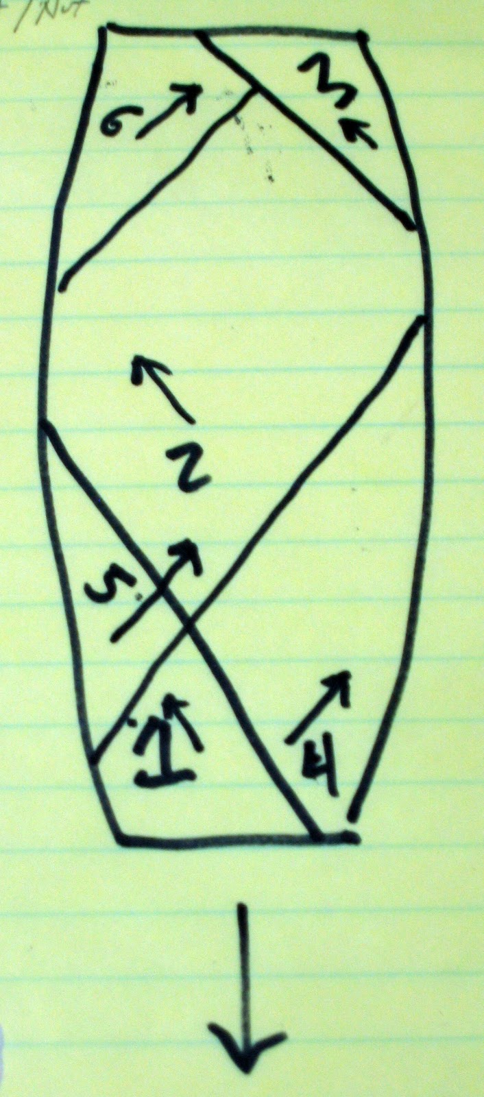
The part is installed per normal (flox, 2 BID tape the seams, ect) and then an additional 7-ply reinforcement is added across the seat belt attachment tube and along the floor approx 6".  I tried this as one 7-ply layup and it worked ok but I didn't anticipate that the 7 layers of glass would be hard to lay down correctly over the attachment tube.  I got it down ok with no air bubbles but was worried for a little bit.  This is also done on the front seat and I did it the same way...probably shouldn't have...I wasn't as lucky getting it all down properly and had a few air bubbles to fill.  I also widened and lengthened each piece of glass by 1/2 " to allow for a smooth transition of the layers.  The black lines you see are my sharpie marks for cutting.  You can see that the plys got a little unruly while laying them down but it came out ok.  I don't know how some builders get such neat, straight, and pretty glass work...I just can't seem to do it.


TIP:  If I were to do it over again, I would follow a tip from Marc Z in the archives and split the length of the plys so that I could lay up alternating plys on each side and get each ply to lay down correctly across the top, overlapping them from each side across the width of the duct.  You'll have 7 ply's on the floor but 14 on top of the duct.

Ok....seat belt attachments done...time to check back in with the headrest.

cab


Ch 8.6: Outside Seat Belt Attachments

Next is the work to install the outside seat belt attach points for the front and back seats.

The outside attachments involve a birch reinforcement piece cut to fit the angle of the fuselage sides and bottom at the lower longeron. These are floxed in and glassed over...2 fwd, 2 aft.

On top of the birch supports are mounted 2" wide aluminum angle brackets that will be used to connect the seat belt.  These are cut from a piece of AL angle, holes drilled, and then they are used as templates to drill the holes through the birch support and the fuselage for the mounting bolts.

No Step.  Normally you would also install an exterior step at the same time that matches up with the pilots left seat belt attach point,,,but on the exterior of course.  As of right now, I've decided not to install a step.  I'm tentatively planning to modify the plane with extended strakes (aka Cozy Girl Strakes) to provide more elbow/storage room inside and if I do that, the step would be in the wrong place.  If I do anything, I might consider a retractable step like Marc Z installed.

Installed birch support, glassed & drillled.
Ready to install aluminum bracket.
Deviation:  As with a few other builders, the bolts to attach the brackets were not quite long enough.  I don't know if this is because some of us aren't counterboring the outside of the longeron deep enough or what, but I didn't want to go too far.  Your mileage may vary.  Marc Z. recommended in an archive email not to counterbore the hole more than approx halfway through the thickness of the longeron.  Well for me, that meant getting bolts that were just a bit longer.  I ended up using -AN-525-416-"18" instead of -"16".


After cleaning the brackets with Alumiprep and Alodining them for corrosion protection, I floxed them to the hardpoints and installed the bolts.

UPDATE (08/31/13):  I ended up using one set of "-16" bolts in the front passenger side.  The -"18" was a little long.  I guess I counterbored that side a little deeper than planned.


cab

Saturday, August 24, 2013

Ch 8.1 - 8.5: Headrest - Part 1/2

Ch 8 is fairly short and deals with a few interior details.  It starts with the shoulder support and headrest.

Like many builders, I'm not a big fan of the triangular shaped headrests in the plans.  They serve the purpose I suppose but they look like something that you would find in the Conehead's car.  They just doesn't fit with the rest of the curved design of the Cozy.

For the Baker Cozy, I want shorter headrests that fit

1986 Saab 9000 Turbo Headrests (from John Slade's website)
the styling better.  Looking through other builders blogs, I found a couple of people who used Saab 9000 Turbo headrests from the late 80's.  They look great and they curve down your neck to provide better support.  I'd like to find some of these if I can...or something like them.  (update below)


Until then, I can only cut and assemble the foam for the shoulder support because I need to install whatever mechanism is needed to hold the headrests before I can glass anything.  Here is a pic of the shoulder support assembled with dry wall screws...waiting for me to find some headrests.  I'll create a part II update for this this when I resume work on it.

So for now...I'll press on with steps 6 & 7 of Ch 8.

cab


UPDATE: (08/24/13...yea..same day I know)  I got to searching the internet for Saab headrests and could not locate the 9000 versions like the ones above anywhere...I think they're just too old.  I did however find some similar ones from an 03 Saab 9-5 and went ahead and bought them off Ebay...$39 each.  I'm hoping they work out.  They look like they will provide the same kind of neck. and head support and they look much better than the Conehead style IMHO.


Sunday, July 28, 2013

The Annual Migration of the Domesticated Aviator...

And it begins...the 2013 migration to Oshkosh for Airventure.  10,000 plus airplanes and 500,000 aviation enthusiasts at what will be one of the world's busiest airport this next week.  Can't make it this year but maybe in 2014.  And of course one day...to realize every homebuilder's dream...to fly their own creation into OSH.

This was at noon today...all the blue aircraft are headed to Oshkosh.


at 1pm...


and around 5:30pm...still going strong...

Whooo Hooo!


Thursday, May 2, 2013

Ch 9: Main Gear & Landing Brake

I'm not quite ready to start Ch 9 yet but my main gear bow and nose gear strut arrived from Featherlite so I had to share.  In Chapter 9, I'll build up and install the main gear, install the axles, wheels, & brakes, and install the landing brake hinging and actuator.  It's a fairly long chapter, only 6 steps but there are 62 figures which gives you an idea of the number of details to be attended to. After this chapter, the blue canoe will start looking more like a vehicle of some sort instead of a boat.

Main Gear Bow and Nose Gear Strut (floor)

cab

Sunday, April 21, 2013

Ch 7: Glassing the Sides (2 of 2)

Vrooom Vrooom...Check it out!!  A major milestone reached...we can finally sit in the Cozy and make airplane noises.  There is still a long way to go but it sure is nice to finally have something that's starting to be recognizable...at least to me.

Me and my co-pilot trying out the size of the fuselage

Glassing the sides was fairly uneventful.  It's a very short paragraph in the plans that took me about 9 hrs each side to accomplish.  Thanks to my friend and co-worker Bryan who helped me with the starboard side.  It only cut an hour off but having an extra set of hands sure made it easier.

I did have a little trouble on the port side so I'll offer a tip to help.

Left side: 23" wide 3rd ply for fuselage
Right side: 3", 4", & 5" reinforcement strips
TIP:  I wasn't too happy with the way the pilot side UND 3-ply top reinforcement came out.  Glass threads kept peeling off the UND and some ended up in a rope-like clump creating a noticeable ridge in the glass.  To avoid this on the other side I used some low stick tape (the blue painter stuff) to mark the edges of each reinforcement before I cut the glass.  I marked a 3" width of glass, then an inch wide piece of tape; 4" width of glass, then another inch of tape, etc.  If you measure it out correctly you can layout all three reinforcements right next to the 3rd ply of UND that covers the entire length of the side. (see pic)  With the tape in place the threads will stay put.

Once taped, you can cut the strips apart down the center of the tape.  Once glassed in place, simply fold the taped part up and run down the length with your electric scissors leaving a nice clean edge.  Using this process, the starboard side came out much better.  I'll be doing this with all my UND strips from now on.

A selected 6" x 6" area with air specks scattered throughout.
OOps, AIR...Again!
After pulling off the peel-ply on the starboard side, I found that I had an inordinate amount of air in the layup from behind the front seat all the way back. It appeared from the grain it was in the first layer next to the foam.  DRAT!  I thought I had conquered this problem.  The port side went great with almost no air at all.  I guess I just couldn't see it.

The inspection criteria says that no more than 10% of  any 6x6 section can have air.  The pic to the left shows a sample 6x6 area.  The trick is determining if you've reached that magic 10% coverage.  Depending on interpretation, the 10% rule is meant for critical areas like wings, canard, etc that take stress.  According the Marc Z from a forum email in 2006, you don't have to be as conservative outside of those areas.  I'm trying to determine if I have a problem or not.  I'm consulting with a fellow builder before I decide if anything needs repair and I'll update the post on my outcome..

Ch 7 Done!  Now to start adding stuff to the fuselage...fun fun!

cab

Tuesday, March 26, 2013

Ch 7: Glassing the Sides (1 of 2)

Sorta like cooking chicken...only different...
It would be difficult and messy to glass large vertical surfaces like the sides so the plans have you build some A-Frame pivots to aid in putting the fuselage in a position that makes it easier to work on.
Cozy builders call this...The "Rotisserie."

The plans don't give you many specifics about how to do it but they do give you enough basics to figure out your own solution.

Firewall Attachment
F22 Attachment
The plans suggest using the hole in F22 that would be used for the gear crank shaft but I don't know if I'll have one so I haven't drilled it.
They also suggest drilling a hole in the firewall but you would have to repair that.

For F22, I used clamps to hold my A-Frame between two boards.  For the firewall, I used two small holes that I had already drilled to locate the control rods and I bolted a 2x4 to them.  Then I put a hole in the 2x4 for a 5/16th pivot bolt.

You'll need to make the pivot points about 24" off the ground to be sure the fuselage clears the floor when turning.  (UPDATE (3/29/13):  You'll notice I made my A-Frames with a 45 degree angle.  I suggest making them more like 30 degrees between them.  At 45 degrees the feet are quite a bit wider than the fuselage and I keep tripping on them.  Maybe I'm just clumsy :-).

Right side up
Roll it around for glassing the
sides or working on the inside


TA DAAA!
The "Rotisserie" in Action


Time to glass the sides, cab

Saturday, March 23, 2013

Ch 7: Contouring the Fuselage Top

She's back upright again and now it's time to get the sides ready to glass.

No...not the saw...
First I made room for where the canard will go by cutting out the the fuselage forward of the F28 bulkhead and across to the cutoff tabs on F22.  Cutting on your fuselage is a little nerve racking...it just doesn't seem right.  :-(    I used 3 different saws for the process...my big crosscut saw, a mitre box saw, and a small drywall saw.

Ready for a canard now.  Note the square top edges
 of the fuselage sides as compared to the pic below.


It was actually much easier than expected and it came out great.  It will really look great when there's a canard mounted there!


Sanding forms for the
3 templates


Shape it up...
Next is the contouring of the top sides.  Just like I did on the bottom, I built a sanding form for each of the templates used on the top.  I started at the back with the D-D template then focused on the C-C template which is used from around the IP all the way to the seatback.  Once the C-C work was near perfect, I moved up to B-B and then to A-A.  I think doing it this way (back to front) helped me blend the curves along the sides pretty easy.


After getting A-A, B-B, and C-C  blended well, I then went back to the aft section between the seatback and the firewall.  I thought blending this section was going to be much harder than it was.  It's a long distance and the two templates are very different.  I first picked a point at the back where I wanted the shape to match the D-D template completely.  The plans say just ahead of the spar cutout...I chose a point a few inches aft of where the doubler starts.  Then I drew a line from the blue/white foam join line at the seatback to the D-D point I chose.  This forms a bit of a long triangle on the side.  Then I simply used my 22" aluminum Perm A Grit sander lengthwise to gently sand nice blended corner using that line as a guide for the blue/white foam join line.  I think it looks great.
A gentle blended shape from the seatback to the firewall

Port side complete...now rinse, wash, repeat on the starboard side
 Onward, cab

Monday, March 18, 2013

Ch 7: Glassing the Fuselage Bottom

Here we go again...
This is another large layup.  Don't believe the plans that say it should take you 3 hrs.  Remember, Nat had built at  least 2 other Aircraft before building the Cozy IV.  Even with that, I find it hard to believe he did this in 3 hours.  Plan on making it the day's activity and don't set yourself up to have to be somewhere at a certain time...you'll rush...and make mistakes.


A couple of thoughts...
Layup Map
- Make sure the shape and surfaces are what you want.  If it's not right before you glass, it won't be right afterward either and you'll just have to add micro to fix it anyway.  Glass is not a filler.


- Pre-cut the glass and mark which is which on the cloth.  Also make a map to follow just to make sure you don't forget which piece goes where in the middle of your work.
- Use longer pot life epoxy so your not rushed.  I use Aeropoxy so I used their 3665 hardener which has a 90 min pot life...worked great.
- Wet out only as much glass as you can reasonably work with at one time then move on to the next section.


Only 11.5 hrs later...done.  I was very pleased with the results...only a few small dry spots found that were easily fixed.  The slightly off colored piece of  glass on the left front was from using the last\bit of some older hardner.  It colors more and more rusty red with age but still works the same.

Glassed Bottom.
Onward, cab

Sunday, March 17, 2013

Ch 7: Bottom Antennas

About Antennae
Electronic navigation and communication require antennae.  The great thing about composite, or plastic, airplanes as they are called, is that you can embed many of the antennae under the skin of the aircraft.  Since ATC radar can see right through foam and fiberglass, it doesn't matter that the antennae aren't mounted on the exterior like they need to be for metal aircraft.  The benefits are a nice sleek looking airplane with no unsightly antenna protrusions and less drag since there's nothing hanging out in the air stream to slow this bad boy down.  It's certainly not much drag but you would be amazed at how all the small sources of drag can really add up.

RST Antenna Kit
Per the plans, I'm installing RST designed copper tape antennae except instead of using RG-58 coax, I'm using RG-400 throughout the entire aircraft.  You can find several recommendations in the archives for it.   RG-400 is similar 50 ohm coax that has replaced RG-58 as the standard for aircraft antenna feed lines   It has a stranded center conductor and is double shielded which is needed for the transponder and GPS transmit lines...oh yea...and quite a bit more expensive.  The best price I found was at B&C Specialty at $2.55/ft or $2.35/ft if you buy more than 50ft.

I'm installing the following systems that will have antennae "buried" into the structure.
- Dual radios - 1 antenna in each of the vertical winglets at the end of the wings
- Dual Navs - 1 antenna in the canard, 1 antenna in a wing
- Marker Beacon - 1 antenna on the fuselage bottom
- Glide Slope - 1 antenna on the fuselage bottom
- APRS - Automatic Position Reporting System used for flight tracking via the internet - 1 Ant in the wing

Other non-copper tape antenna that will be installed...
- Transponder - Installed in the nose
- GPS - probably in the nose

Fuselage Antennae
MB Solder Joint
On the bottom of the fuselage, I'm installing the marker beacon (MB) and glide slope (GS) antenna.  After determining where to install them, I oogered out the channels in the foam for the coax keeping in mind RSTs guidance on proximity and size of metal objects.  You need to pay attention to where the nose gear will retract and the landing light if you're using the plans design...which I'm not.  Then soldered the coax to the copper tape of appropriate length based on RSTs instructions.  After everything is installed, I potted the solder joint and filled the channel with micro.

MB & GS Antennae trial installed just before
permanent install and fill.
GS Solder Joint
To the left is my antenna layout before final install.  The marker beacon is on the right and glide slope in the center.  I punched the coax through at a point just fwd and to the pilots side center of the instrument panel.  Be sure avoid the wheel well area.

Note the oogered channel running diagonal back to the front of the IP...I changed the routing of the MB coax to keep the appropriate distance from the tip of the GS antenna and any metal.  I'm not sure if I had to do this with feedlines but I figured I would play it safe.  You can see the re-routed coax now comes toward the front more and then over to the punchdown.


TIPs:  You'll need some tools.  Based on a recommendations from an RV builder site, RST, and other internet locations, here are the tools I purchased.  Coax stripper: I bought a Paladin 11255-LC CST and it worked great.  BNC crimper: I purchased an Eclipse Lunar 300-054 crimper frame and the 300-038 die.  For soldering supplies I got Kester 44 63/37 solder.

Now for the fun...time to glass the bottom.  Onward.  cab


Sunday, January 13, 2013

Ch 7: Prepping the Landing Brake

The landing brake was cut out during the building of the fuselage bottom...now it needs to be somewhat re-installed before the bottom gets glassed.  The area around it get's routed out 1/16" below the surrounding area and the brake is tacked in place with 5 min epoxy.

Routing out the area around the landing brake
I used a router tool I have for my Dremel to prep the area around the brake.  This worked really well.

The router tool for my Dremel made it very quick
to carve out of the 1/16 depth of foam.
After the brake is tacked back in place and the surrounding area routed 1/16" down, layers of 1" wide duct tape, approximately 1/16" thick, is placed around the brake essentially forming a larger brake door surface. This is temporary as epoxy doesn't stick well to duct tape.  It's hard to see now, but in chapter 9 the brake will be cut back out around the tape, the tape will be removed to make way for glass on the other side, and the whole thing will be hinged in place and the actuator installed.  After that, the remaining area that was routed out (see pic below) will be filled with micro to form a nice seamless blended bottom across the landing brake.

(Deviation) Notice that I decided to extend the hinge all the way across the brake vs the plans shorter hinge.  I'm hoping this will help eliminate any tendency for it to warp like some others builders have seen.

The landing brake ready for the bottom glassing.


Fergelli FA-PO-150-12-4 Actuator
 Since I mentioned the actuator, I plan to install a Firgelli electric actuator vs the manual plans version.  This actuator has been used by several other builders, has a 4" throw, 150 lbs load, limit switches at each end, and a feedback potentiometer so I can wire it to my EFIS and know what position the landing brake is in at any time.  More on that when I install it in Ch 9.


One more step before glassing the bottom...antennas!  Onward, cab


Saturday, January 12, 2013

Ch 7: Contouring the Bottom

Curves
Time to turn this box into something with smooth sexy curves !  After sanding down the NACA scoop and sanding the foam to shape around the rear bulkhead area, the next task is to shape the aft end around the firewall so it smoothly flows into the forward fuselage.

The first step is to remove the foam covering the longeron and LWY from 5.5" ahead of the FW aft.  This is where the main spar will fit and you will need this area to tie in the glass when it's installed.  You also need to bevel the edge of the remaining foam into the longeron and LWY so glass from the fuselage can smoothly tie into those parts.  Some builders beveled the entire length of the foam edge but indications are that this is only needed where the foam leads to the longeron or LWY.  The pics below show my interpretation of how this is supposed to be done.

Aft fuselage side before foam removal
Aft fuselage side after foam removal


Aft fuselage side after sanding the transition
from the fuselage side to the firewall
Next, per plans, I sanded a smooth transition from the FW to approximately 25" in front, and at the bottom of the fuselage (top in pictures since it's upside down).  This is kind of a nerve racking task because it's a little hard to know if you're sanding enough or too much to get to the shape you need.  The FAQs give a pretty good description of what you're looking for and I also consulted multiple other builder sites for pictures of their results.  You'll likely start to uncover the electrical channel...if you do it's time to stop.  Here is what I ended up with.


Corners
Corner after the initial 45 degree shaping cut w/ a saber saw
Now I worked on shaping the squared corners of the bottom from front to back.  As the plans recommend, I used a jig saw to cut a 45 degree cut along the edge but I didn't cut all the way down to the longeron.  Instead, I cut a little shallow and used a belt sander to get down closer (although I still didn't get to the 1/4" exposed longeron...but close).


Here you can see my shaping tool
with center marks and my corner line.
Very smooth and even results
(Tip)  Using the template from the plans, I built a sanding tool and began the back and forth until I got a nice rounded shape.  I marked the side of the tool so I could keep it centered on the longeron.  I also ran a line down the center of the corner with a sharpie.  That way, when the line started to disappear, I knew the corner was filling the template tool and I was almost there.  Be sure to make long consistent strokes.


After the front half is sanded to shape to about the middle of the landing brake, the area starts to change so that it blends nicely into the aft shape at the landing gear bulkheads.  This was the hardest part to get correct and make sure both sides match.  I over sanded a bit in some areas and had to go back and fill/sand with micro to get it correct.  Here's how it ended up.


Onward,
cab

Sunday, January 6, 2013

Ch 7: Gear Area & Rear NACA Scoop Prep

There are 4 birch pieces that get cut and then installed in the aft section.

Parts A & B are simple triangular pieces that provide a solid backing for exterior foam.  Note that the craft sticks were great to hold the pieces straight up while the flox cured.

Parts C & D are polygons that form bracing between the firewall and aft landing gear bulkhead.  I had to adjust the dimensions for parts C & D a bit to fit properly between the FW and LG bulkhead.  It's not real clear in the plans but the firewall drawing shows part D to be installed horizontally.  When I did that, I ended up with a small gap where the vertical and horizontal pieces come together.  Other builders have had this same issue and it is noted in the FAQs...so I filled the gap and moved on.  

Backside of Parts A & B (left) and C (right) while curing

Front side of A, B, & C showing the space where foam fills in.
Also, you can  see the NACA scoop to the left
before it was sanded to final shape.

Parts C (vertical) & D (horizontal) installed
w/ flox  filling the gap between.  The open
space gets filled  w/foam and shaped
 to match the bulkhead/firewall.


Closing out the scoop:
Next the foam for each of these areas was installed along with the PVC foam lining around the aft portion of the NACA scoop where it leads into the cowling.  This was then sanded down to match the outline of the firewall and aft landing gear bulkhead.


Rear bulkhead area completed and ready for glassing.
Between the bulkheads is where the landing gear will be installed.
An access panel will be formed to cover the gap in Chp 9.

To Joggle or Not to Joggle?
The plans call for cutting a 1/8th inch joggle into the edge of the NACA scoop at each of the landing gear bulkheads and the installation of some threaded aluminum slugs.  In fact, the bottom is installed with this joggle already in mind.  This is to allow for the future installation of the landing gear cover.  Getting glass to lay down properly on these joggles is notoriously difficult.  I decided NOT joggle...in fact I filled in the gap formed on the installation of the bottom with a sliver of PVC foam.  I plan to follow Wayne Hicks landing gear access door plan as it's easier and looks to be a better fitting part when complete.  

Onward, cab