Close-Out the Outboard Ends
 The first task was to clean out the outboard ends of each elevator torque tube and install the NC-6 insert end pieces to cap them off. In doing so, I had to drill two holes, one for a rivet (in front in the picture) that holds the NC-6 in place, and the other on the bottom where a small threaded lock screw will eventually lock in the stainless hinge pin. The bottom one was a little nerve racking because your drilling blind into an already threaded hole. Missing the hole would be bad and blowing through the torque tube and into the threads would screw them up. TIP: I did this work in a serial manner...install rivet, then figure out the blind hole to drill. What I should have done was use the rivet to hold the part in place (but not permanently squeezing it in) while I located the blind hold to drill. Then removed the part, drilled the hole, and then permanently installed the part with the rivet. That would have eliminated the risk of ruining threads in the part. Oh well, this is an educational activity after all! I'll probably be saying that a lot.
I did my best to measure the location of the hole using a digital caliber and transferring the location onto the outside of the torque tube. I was dead on the first time. On the second I was close enough but I think I ate up a few threads in the insert. There are clearly some still there so all is good.
Uh Oh...Questioning the Dimensions
Now I laid all the parts out on the bench end-to-end to make sure everything was looking correct before I started drilling holes. I compared the hinge locations in the hardware to the hard points embedded in the canard and noticed that the first inboard hinge points were not falling quite in the middle of the hard point at B.L. 15.6" per plans. It was only off by .1" at 15.7" and would work fine, but it shouldn't have been off at all...what was up?
I did multiple measurements of all the parts and hard point locations and what I found was that the
Cozy Girls CZNC-12A offset torque tube dimensions were slightly longer than the plans on the inboard side of the hinge slot which made the overall length of the part .2" longer than the plans indicate. So it that was the case, why weren't my elevators .2" longer on each side? Something had to be wrong in the plans. Additionally, only the first hinge slot is off and by only .1". It falls at B.L. 15.7" vs the plans 15.6". The outer two hinge locations were per plans and when I measure the overall length of the elevator assembled on the bench it comes to 140.8" just as it should be. What's going on here? The only answer I could come up with was that are multiple places in the plans dimensions for the offset torque tube as well as hinge hard point locations in the canard that must be incorrect.
 I spent way to long on this for a .1" difference but I wanted to understand what was going on. Here is what I found. I already mentioned the CZNC-12A being .2" longer than plans spec. Additionally, I believe the B.L 15.6" callout for the location of the center of the first inboard hinge hardpoint and hinge slot in the CZNC-12A is wrong in the plans (Ch 10 pg 7, fig 48, and Ch 11 pg 2). I know this because if you starting from the center line and add up the length of the center torque tube (15.1") and the length of the plans dimensions for the CZNC-12A up to the center of the inboard hinge slot(.265" +.110"), you find the location of the center of the inboard hinge should be 15.475" or 15.5" rounded up instead of 15.6" per plans. Now, when you use the Cozy Girls .2" longer CZNC-12A, it places the hinge slot at B.L. 15.7", .1" outside the plans incorrect 15.6" callout but .2" outside the calculated location based on the plans .2" shorter CZNC-12A dimension. The other two hinge slots in the elevators are correctly called out and work perfectly with the Cozy Girls part.
Ok...what's the bottom line? My conclusion is that the plans .265" dimension inboard of the hinge slot in the CZNC-12A, Chpt 11 pg 2, is incorrect and should be .465" like the Cozy Girls version of the part. And, the callouts of the B.L. location of the inboard most hinge hard point and the matching CZNC-12A hinge slot, Ch 10 pg 7, fig 48 and Ch 11 pg 2, are incorrect and should be B.L. 15.7" instead of 15.6". Fortunately there is enough margin in the location of the 1" wide hinge hard points to account for this slight difference. So if you built it to plans, and used the Cozy Girl parts, all is still good. If however you built your own CZNC-12A to the plans dimensions, your elevator length is likely .2" too short on each side and none of the hinge hard point centers will match the torque tube hinge slots correctly. I remember in Chapter 10, when laying out the hard point locations, it recommended laying out the elevator torque tubes to check the hinge locations. This would have been smart to do.
I'm guessing that sometime way back the Cozy Girls knew to correct for this in order to make the overall length work out correctly and that the plans somehow didn't get these dimensions updated. I don't know for sure. Searching the archives (which BTW I usually do before starting a chapter and didn't) revealed that others found the same anomaly with the offset torque tube but nobody seems to know exactly why. Reported discussions with the Cozy Girls also showed they apparently don't remember why the dimension was different. There is no mention of the hard point location possibly being incorrect. Some builders adjusted the length of the center torque tube to compensate. Others didn't, but it seems to me that if you do that you'll end up with slightly shorter elevators and will have to sand your canard slightly shorter to obtain the .1" elevator-to-canard tip gap. I'll go back and put a link to this discussion on my canard build page so future builders will at least be aware of this and can adjust the inboard hardpoint slightly should they so chose. A bigger issue is that anyone building their own CZNC-12A needs to know the plans dimensions are incorrect.
Puttin it All Together
 |
| Offset torque tube, "spool" (center torque tube), Drill Hog drill bit set, and reamer |
----------------------------
TIP: Let me say that you want to be careful drilling holes in any control mechanisms. You can easily accidentally drill them slightly over-sized and over time they could develop slop...not something you want in your control system. Some builders use taper pins, which are great, but expensive. Some experts on the forum suggest that there's really only one place that makes sense for taper pins and that's the rudder torque tube assembly because of the amount of torque involved when applying the brakes. This is probably what I'll do. For the rest of the control system I'll stick with the plans bolts and if they give me any problem later I can always switch to taper pins. I doubt that will be the case.
So, to ensure I didn't over-drill a hole, I started with a pilot hole per plans and then stepped up to the final size a little at a time. I stepped up 5 numbered drill sizes at a time and stopped with a drill that was 2 numbered drill sizes smaller than the bolt. Then I used a reamer for the finish size making sure the reamer matched the actual bolt being used. This resulted in a nice tight fit.
Get yourself a set of numbered drill bits, 1 thru 60. I got mine from Drill Hog on Ebay and they have a lifetime warranty. Break one, send it back, get another.
----------------------------
 |
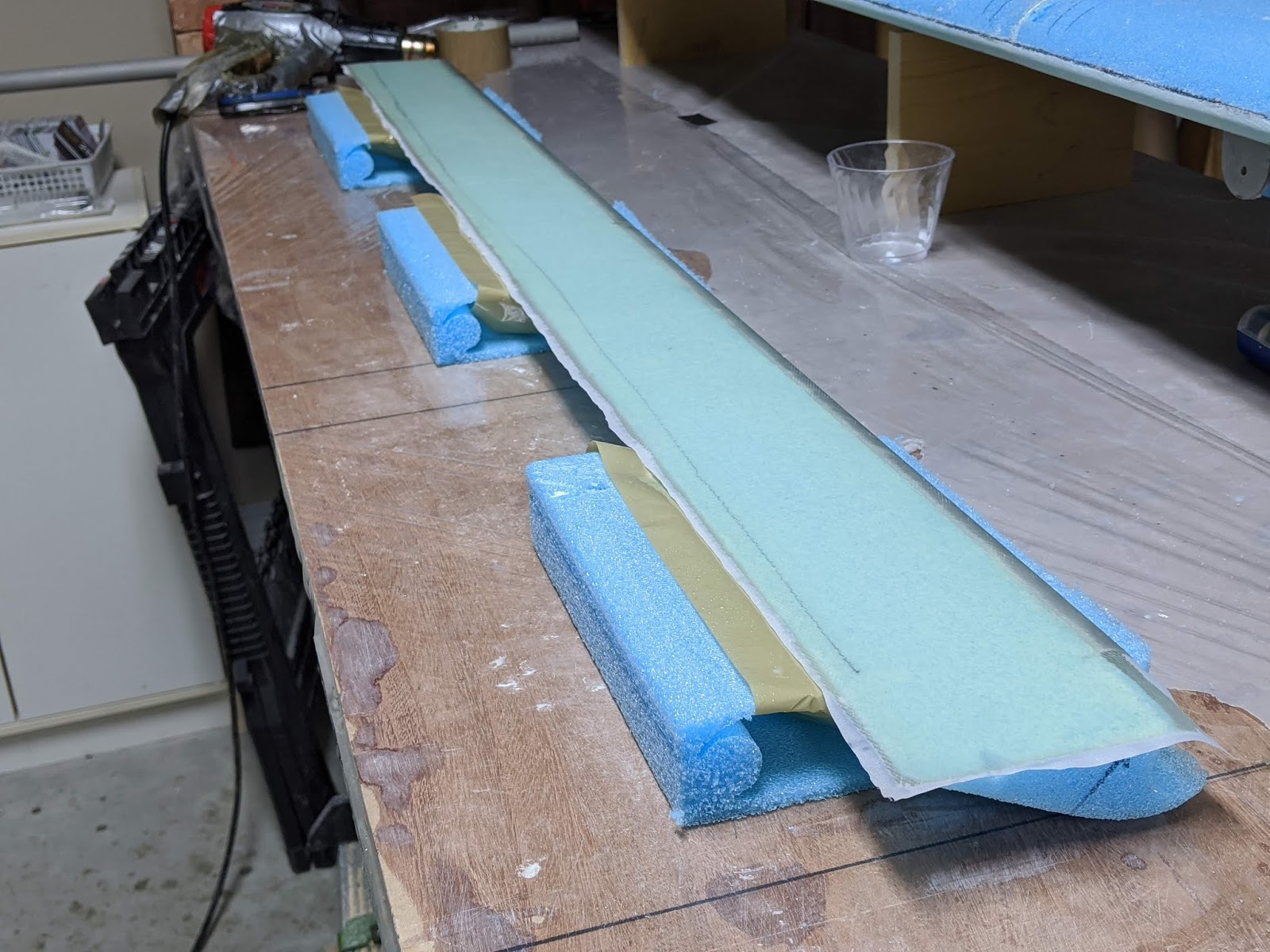
| Elevator assembly jigged on the work bench |
The next two attach the elevator torque tubes to the other side of the offset torque tube. This requires aligning the entire elevator assembly, bondo'ing it to the work bench, and dialing the center spool piece to the same position where the hinge pin will insert properly.
 |
| Close up of one side showing the two bolts on each side of the offset torque tube. Note: Not done yet was the last step which was to auger out foam from the inboard end of the elevator in order to attach the back side nut on the elevator torque tube bolt. |
The only thing left to do is auger out the inboard foam to allow installation of the back side washer and nut on the torque tube bolt. The augered out foam will get filled in later after the inboard side of the elevators get trimmed to match the fuselage sides.
NOTE: The plans don't say it but the bolt length assumes you put AN960-10 washers under the head and nut of these bolts. You should always put the appropriate washer under bolt heads and nuts.
Onward to hinge the elevator to the canard !